One of the focus areas for INGITEQ is automation and Controls, so this blog from our VP of Engineering, Greg Young, provides a technical description of how we approach Proportional Integral Derivative (PID) controllers or PID Loops. PID is mathematical logic that allows control devices to function accurately and optimally. For those not versed in controls engineering, this provides a glimpse “behind the curtain” of the world of automation.
- Steve Justice, PE – INGITEQ Chief Operating Officer

Many people across different industries have similar goals. Increased throughput, a more stable process, reduced downtime, and realizing energy savings are just a few that all of us can appreciate. There are many ways to achieve these goals, and properly understanding and tuning a PID loop is one great way to do so.
What is a PID loop? A PID loop is a type of control method that allows a controller to receive data and make decisions on how to adjust a process. For example, a controller can receive data from a pressure transmitter and control the speed of a pump motor to increase or decrease pressure in a pipe. There are a few components of the PID loop to keep in mind to fully understand how to properly tune the loop.
- (PV) Process Variable = the part of the process that needs to be controlled
- (SP) Setpoint = the value the PV needs to be controlled to
- (CO) Controller Output = the signal sent from the controller to a field device
- Controller Error = the difference between the SP and the PV
- KP = Proportional Gain (no units)
- KI = Integral Gain (1/seconds)
- KD = Derivative Gain (seconds)
How does each of the tuning parameters affect the PID loop? The following is a useful equation named the Independent Gains Equation. This equation is used by many industrial controllers and PLCs and is a good one to consider when looking at how each parameter affects the controller response.

Where the blue portion is the proportional component, the yellow portion is the integral component, and the green portion is the derivative component.
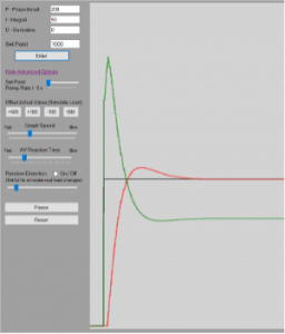
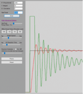
The proportional gain (KP) affects how much the controller output (CO) changes due to a change in controller error. When there is a change in error in the system, the controller multiplies the change in error by the PG and adds that value to the controller output (COn=COn-1+KP∆E). For instance, if one has a large PG the controller will be more sensitive to changes in error. This can help one achieve a fast response, but it can also lead to overshooting the setpoint or erratic oscillations. One can see in Figure 1 and Figure 2 below the difference in a small and large KP.
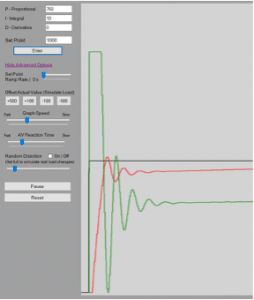
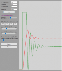
The integral gain (KI )affects how quickly steady-state error is eliminated. The controller multiplies the error by change in time and by the integral gain (COn=COn-1+KIE∆t). The controller then adds that value to the controller output to help reduce any steady-state error that the proportional gain does not eliminate. A higher KI will eliminate steady-state error faster, but can also cause the system to be more erratic. One can see the effects of a low and high KI below in Figure 3 and Figure 4.
The derivative gain KD is not as commonly used when tuning as the proportional gain and integral gain are. The derivative gain looks at how fast the controller error is changing and uses that to decrease or increase the controller output (COn=COn-1+KDEn-2En-1+EN-2∆t). It applies a braking force when we are approaching our setpoint too fast. A higher KD value can help smooth out a process response to disturbances, but can also introduce other issues. Derivative gain can introduce an issue known as derivative kick. The derivative component can be very sensitive to noise in the system. If the measurement of the PV is noisy, the controller might react too strongly to what it perceives as a change in PV or change in error. If the KD is too high, this can cause the controller to incorrectly assume that it needs to immediately change its output by a large amount. For this reason, most systems will be tuned with only the proportional and integral terms if a smooth tune can be achieved with only those two components.
How is a PID loop properly tuned? There are a few methods to properly tune a PID loop, and we will consider two of the most popular. The first method utilizes manual techniques while the second employs the use of highly powerful tuning software.
To manually tune a PID loop, one can follow these steps.
- Start with a low proportional gain (KP), an integral gain (KI) of zero, and a derivative gain (KD) of zero.
- Perform a bump test on the process by raising the desired setpoint (SP) and letting the process variable (PV) level out. The PV should level out below the desired SP.
- Increase the KP until the PV reaches the SP, begins to oscillate, and the oscillations grow in magnitude.
- Decrease the KP until the oscillations begin to grow smaller and disappear.
- Add these two KP values and divide them by two. This is the KP value to use when introducing the integral gain.
- Introduce a conservative integral gain KI and increase until the reaction time is fast but not too aggressive.
- Run more bump tests to see how the process reacts with the proportional and integral gains that have been applied.
- It may be beneficial to add a derivative value to prevent the overshoot and make it more stable if needed. Too high can create an unstable system. A noisy system can also be a bad process to use a derivative component with.
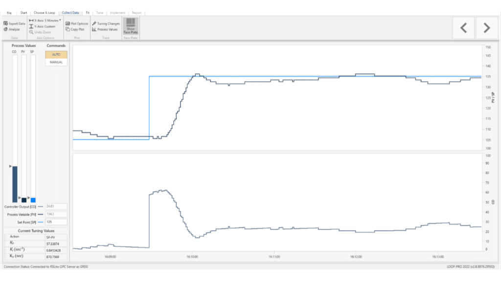
Another popular method for tuning is to use sophisticated tuning software such as Control Station’s Loop-Pro Tuner. Tuning software such as Loop-Pro Tuner can free up valuable integration time when dealing with very complex loops. One can see from the figures below that an odd combination of tuning parameters was achieved for a particular steam heat exchanger tune. The resulting parameter values were a KP of 57.32, a KI of 0.8453, and a KD of 870.8. This would have been very difficult to replicate by hand. There are certain scenarios where proper tuning software can be of great use.
Properly understanding and tuning a PID loop is a great way to achieve many tangible goals in many different environments. Are there ways you can implement this new knowledge in your environment? There are many exciting possibilities!
Contact us today to see how Ingiteq can help!

