Categories
Automation

An Introduction To PID Tuning

One of the focus areas for INGITEQ is automation and Controls, so this blog from our VP of Engineering, Greg Young, provides a technical description of how we approach Proportional Integral Derivative (PID) controllers or PID Loops. PID is mathematical logic that allows control devices to function accurately and optimally.  For those not versed in controls engineering, this provides a glimpse “behind the curtain” of the world of automation.

  • Steve Justice, PE – INGITEQ Chief Operating Officer
Greg Young, VP of Engineering, Ingiteq

Many people across different industries have similar goals. Increased throughput, a more stable process, reduced downtime, and realizing energy savings are just a few that all of us can appreciate. There are many ways to achieve these goals, and properly understanding and tuning a PID loop is one great way to do so. 

What is a PID loop? A PID loop is a type of control method that allows a controller to receive data and make decisions on how to adjust a process. For example, a controller can receive data from a pressure transmitter and control the speed of a pump motor to increase or decrease pressure in a pipe. There are a few components of the PID loop to keep in mind to fully understand how to properly tune the loop. 

  • (PV) Process Variable = the part of the process that needs to be controlled
  • (SP) Setpoint = the value the PV needs to be controlled to
  • (CO) Controller Output = the signal sent from the controller to a field device
  • Controller Error = the difference between the SP and the PV
  • KP = Proportional Gain (no units)
  • KI = Integral Gain (1/seconds)
  • KD = Derivative Gain (seconds)

How does each of the tuning parameters affect the PID loop? The following is a useful equation named the Independent Gains Equation. This equation is used by many industrial controllers and PLCs and is a good one to consider when looking at how each parameter affects the controller response. 

Where the blue portion is the proportional component, the yellow portion is the integral component, and the green portion is the derivative component.

The proportional gain (KP) affects how much the controller output (CO) changes due to a change in controller error. When there is a change in error in the system, the controller multiplies the change in error by the PG and adds that value to the controller output (COn=COn-1+KP∆E). For instance, if one has a large PG the controller will be more sensitive to changes in error. This can help one achieve a fast response, but it can also lead to overshooting the setpoint or erratic oscillations. One can see in Figure 1 and Figure 2 below the difference in a small and large KP.
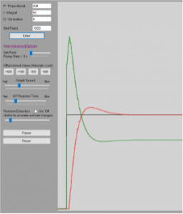
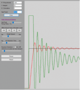
Figure 1: Low Proportional Gain
Figure 2: High Proportional Gain

The integral gain (KI )affects how quickly steady-state error is eliminated. The controller multiplies the error by change in time and by the integral gain (COn=COn-1+KIE∆t). The controller then adds that value to the controller output to help reduce any steady-state error that the proportional gain does not eliminate. A higher KI will eliminate steady-state error faster, but can also cause the system to be more erratic. One can see the effects of a low and high KI below in Figure 3 and Figure 4.
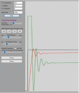
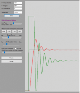
Figure 3: Low Integral Gain
Figure 4: High Integral Gain

The derivative gain KD is not as commonly used when tuning as the proportional gain and integral gain are. The derivative gain looks at how fast the controller error is changing and uses that to decrease or increase the controller output (COn=COn-1+KDEn-2En-1+EN-2∆t). It applies a braking force when we are approaching our setpoint too fast. A higher KD value can help smooth out a process response to disturbances, but can also introduce other issues. Derivative gain can introduce an issue known as derivative kick. The derivative component can be very sensitive to noise in the system. If the measurement of the PV is noisy, the controller might react too strongly to what it perceives as a change in PV or change in error. If the KD is too high, this can cause the controller to incorrectly assume that it needs to immediately change its output by a large amount. For this reason, most systems will be tuned with only the proportional and integral terms if a smooth tune can be achieved with only those two components. 

How is a PID loop properly tuned? There are a few methods to properly tune a PID loop, and we will consider two of the most popular. The first method utilizes manual techniques while the second employs the use of highly powerful tuning software. 

To manually tune a PID loop, one can follow these steps.

  1. Start with a low proportional gain (KP), an integral gain (KI) of zero, and a derivative gain (KD) of zero. 
  2. Perform a bump test on the process by raising the desired setpoint (SP) and letting the process variable (PV) level out. The PV should level out below the desired SP.
  3. Increase the KP until the PV reaches the SP, begins to oscillate, and the oscillations grow in magnitude. 
  4. Decrease the KP until the oscillations begin to grow smaller and disappear. 
  5. Add these two KP values and divide them by two. This is the KP value to use when introducing the integral gain.
  6. Introduce a conservative integral gain KI and increase until the reaction time is fast but not too aggressive. 
  7. Run more bump tests to see how the process reacts with the proportional and integral gains that have been applied. 
  8. It may be beneficial to add a derivative value to prevent the overshoot and make it more stable if needed. Too high can create an unstable system. A noisy system can also be a bad process to use a derivative component with.

Another popular method for tuning is to use sophisticated tuning software such as Control Station’s Loop-Pro Tuner. Tuning software such as Loop-Pro Tuner can free up valuable integration time when dealing with very complex loops. One can see from the figures below that an odd combination of tuning parameters was achieved for a particular steam heat exchanger tune. The resulting parameter values were a KP of 57.32, a KI of 0.8453, and a KD of 870.8. This would have been very difficult to replicate by hand. There are certain scenarios where proper tuning software can be of great use. 
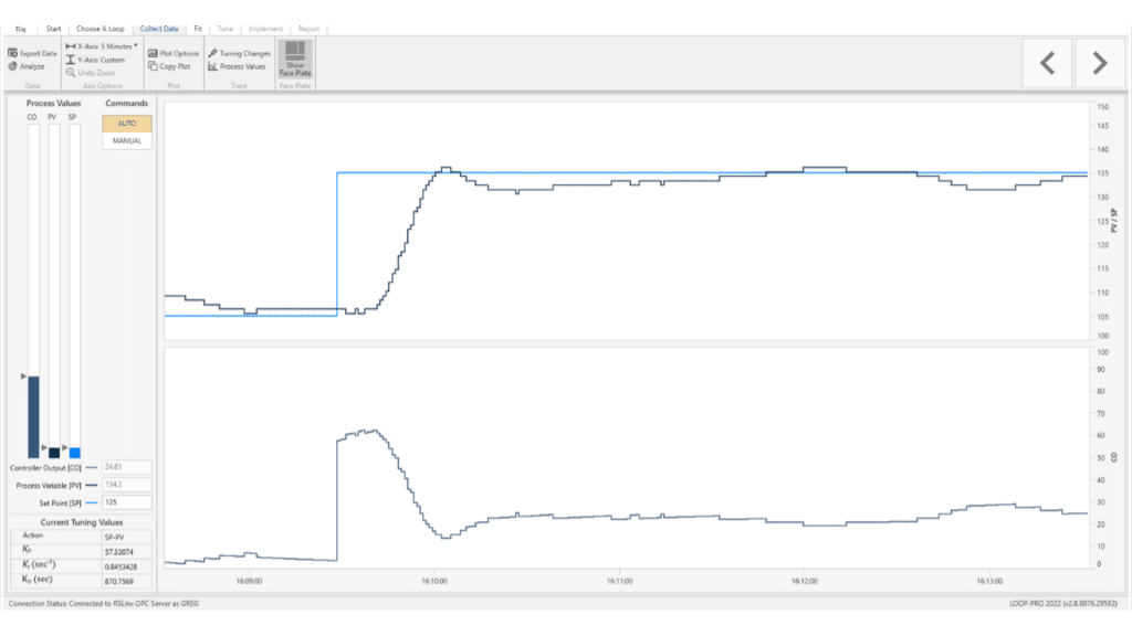
Figure 5: Tuning Results from PRO-Tuner

Properly understanding and tuning a PID loop is a great way to achieve many tangible goals in many different environments. Are there ways you can implement this new knowledge in your environment? There are many exciting possibilities!

Contact us today to see how Ingiteq can help!

Categories
Automation

An Introduction to Automation

Greg Young, Vice President of Engineering | INGITEQ

It’s no secret that automation is a current and positive force, but you may be wondering how exactly to implement new technology in your business process. With the increases in efficiency, reduced maintenance costs, and better working environments, it’s no wonder that automating has become increasingly popular. At INGITEQ, we are experts at identifying the most opportune processes for automation and outfitting a tailored solution. But allow us to bring you behind the curtain so that you can see how automation can benefit your operation. Various methods and tools can be used to introduce automation, including programmable logic controllers (PLCs), variable frequency drives (VFDs), automated level control, PID loops, and others. We’re here to explain more about what this can mean for your business.

Commonly used Allen Bradley ControlLogix Programmable Logic Controller.

Programmable Logic Controllers (PLC’s) are widely used to increase efficiency. PLC’s are used to automate manual processes through the use of field instrumentation such as switches, transmitters, and control valves. Processes that traditionally take many steps of slow, manual, non-ergonomic interaction can be streamlined through the use of a simple control panel with pushbuttons or a touch screen interface. PLC’s can also be used to monitor different aspects of processes. Being able to measure real-world data while processes are running gives the ability to see maintenance problems before they arise. There are different ways to do this, including measuring vibration on a pump motor, tracking power consumption, or logging the time it takes for a machine to complete a task. 

PLC’s also introduce safer and more ergonomic tasks for operators to complete. Instead of turning handles on large ball valves, an operator can simply press a button on a screen. An increase in ergonomics has been shown to reduce the number of injuries at a workplace, introduce cost savings, and reduce employee turnover. Another interesting benefit to consider is that with the use of PLCs and today’s network hardware, we can bring operations online so that they can be accessed remotely. So how do you identify whether a PLC would be useful to you? PLC’s are extremely useful in industrial processes of all sorts. In fact, PLCs can be used to automate almost any process. But here at INGITEQ, we might suggest that installing a PLC on your office coffee machine is a bit extreme.

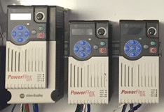
Allen Bradley Variable Frequency Drives

So, what is a VFD? About half of all global electricity is consumed by processes run with machine drives including mechanisms such as electric motors, pumps, and fans1&2. Using Variable Frequency Drives (VFDs), the energy usage of these processes can be decreased drastically. Instead of the motor running at full power whenever it is on, a VFD can cause it to use a lower frequency than what the motor is designed for at a full load. This is typically achieved by referencing a particular parameter that must be met within the process, like flow rate, pressure, or temperature. If the target parameter is being overshot by a motor, the VFD can slow down the motor by lowering the frequency. The target is then met, and energy savings are realized by the VFD. Using a VFD in a system also eliminates the need for other mechanical devices such a flow restrictors. These could be restriction orifices or control valves that further reduce the efficiency of the system by creating additional friction loss and requiring increased downtime for maintenance. In other words, a VFD can be way more effective than flow restrictors.

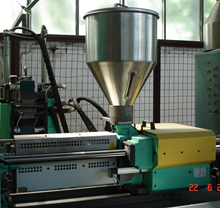
Hopper feeding plastic pellets into an extruding machine3.

Automated level control is another widely used method to use process automation to your benefit. Many processes are currently run without any knowledge of the fullness or emptiness of a tank, hopper, or silo. This can cause a multitude of issues, depending on the industry. If you’re using a silo or hopper to feed a product into a process such as a concrete mixer or seed bagger, automating the level indication and control can greatly increase productivity. If the container becomes empty without the operator’s knowledge, the process comes to a halt. This leads to downtime and lost revenue. By having automated level indication, the operator can be warned when the supply is running low. Other processes have an even more critical need to automate level control. Chemical storage tanks are used in many industries from agriculture to oil and gas. Without automated level control, a tank can be at risk of overflowing and causing damage to equipment or harm to operators. By implementing simple controls such as automated shutoff valves, level switches, and continuous level transmitters, you can introduce greater levels of safety and avoid unnecessary loss of product. The result of using automated level controls is safer operators, a better bottom dollar, and happier management.

PID loops are control loops that can be used for many different processes such as furnaces, wastewater pumping stations, and conveyor belts. PID stands for proportional, integral, and derivative. A PID loop works by referencing a process variable such as a temperature or pressure and comparing that to a process setpoint. The PID loop’s goal is to reduce the error between the setpoint and the measured process variable. If a PID loop’s tuning parameters (proportional gain, time integral, and derivative) are programmed properly, the process can stay very close to the setpoint. This results in greater efficiency and a higher quality process. We may consider this one for your office coffee pot if you ask nicely.

All aside, now that you know more about the types of automation available to you, I challenge you to look around your work environment this week. In what areas can you be saving time and energy? What are some ways that you can provide a better and safer work environment for your employees? Amidst the world, as it is today, in what ways can you bring some of your processes online to be managed remotely at your fingertips? Let’s talk about these opportunities you’ve identified and pair them with our longstanding expertise. Let’s have a cup of coffee. Let’s innovate together.

References:

  1. https://www.eia.gov/todayinenergy/detail.php?id=13431 
  2. https://cleantechnica.com/2011/06/16/electric-motors-consume-45-of-global-electricity-europe-responding-electric-motor-efficiency-infographic/
  3. https://upload.wikimedia.org/wikipedia/commons/1/1d/Tolva_de_inyeccion_de_extrusion_de_polimeros.JPG